Sunday, November 27, 2011

Still More Forward Fuse Construction

I've been staring at these parts for several weeks.  I'd clamp them together then take them apart.  Refer to the prints and clamp them together again.

Kind of like a big jig saw puzzle.  Sometimes it went together good, sometimes not so good.

I finally think I have it and started drilling and Cleco-ing the Forward Fuselage Lower Frame Assembly together.

About 15 parts, maybe more, are used to construct the frame.  I started by marking the center line (CL) down the middle of the fuselage tunnel.
Next, I marked some location marks for the rudder pedal supports, left & right.

I drilled some pilot holes in the fuselage tunnel making a rivet line for the pedal support brackets.

Before drilling, I clamped the pedal support brackets in place.
Just about done drilling for the day.  Looking pretty good & measuring up well to my location marks.

The structure is strong even with just Clecos holding it together.  I know the location it attaches to the main spar, but, not sure how I will support it while fitting it to the spar.
I made a couple of 90 degree brackets to help support the forward floor support structure.  The prints showed 3 rivets.  My brackets are just a tad longer with 2 rivets on each side (4).
Internal shot of station 59.75 bulkhead.  I don't think the squeezer will fit in here.  Looks like it will be difficult to rivet.

Not sure of the riveting sequence yet.  There will be a floor on top and a belly skin on the bottom covering this area.
Speaking of riveting difficulties, riveting out in the tips of the rudder pedal support brackets will be hard to do out near the ends.  Looks tight.

A few more holes to drill then comes the fun part..........in no particular order..........deburing, dimpling, counter sinking, corrosion protection, etc. etc........(not necessarily in that order.)

Later,
Brian

Saturday, November 26, 2011

More Forward Fuselage (Firewall)

The other day I started drilling out the #40 holes to #30.  Getting ready for the final construction of the firewall.

After correctly sizing the holes I deburred the holes and all the edges of the aluminum angles and filler shims.


The order of engine enamel paint came in from Aircraft Spruce so I primed all the Firewall parts with it.  All the aluminum parts.  Not the stainless steel firewall.

My motor mount is white so, I used black on the Firewall parts.

I let them dry overnight.  Before Cleco-ing and riveting the parts together, I wet the mating surfaces with paint, and just before it set, we finished riveting.


The paint will help to prevent moisture from collecting between the surfaces by means of capillary action.  (Thanks for the idea Jerry.)
 
I constructed a fixture on the bench to hold the Firewall firmly while driving rivets.

My friend Tom R. came over and assisted setting rivets.

Looks pretty good.  I like the circular brushed finish of the stainless steel.

The lower aluminum angle attaches to the forward fuselage floor and bracket assembly.  The whole assembly will then rivet to the Firewall along with the lower engine mount brackets.

The next step will be to mount the Firewall in the front of the plane.  Not sure how to do that as yet.

Here is a shot of the lower aluminum angle and floor.  I drilled the pilot holes in the floor and angle.  The center most hole is an alignment hole that will aline with a hole in the Firewall.

The outer ends of the angle need filler shims to adjust for the floor.

Last thing I did tonight was to start assembly of the forward fuselage floor "H" frame.

So, I am making slow but steady progress.  There are a lot of sub-assemblies in the forward fuselage.

Tomorrow I will clean the shop and regroup for next week.         Brian

Monday, November 21, 2011

Motivational collapse (Hey, It happens!)

I didn't get much done this last weekend.  My motivation has gone down as the leaves & temperature dropped.  It gets cold out in the garage and the leaves had to be cleaned up.

I have a four day holiday starting Thursday and I hope to make some progress on the firewall.  The firewall is a key component in completion of the forward fuselage.  (Lots of parts to test fit.  BLARG#$?!)

Drilling out the #40 to #30 size holes in firewall angles and doublers.  Getting ready for riveting exercises to commence.

"Test" fitting the firewall to forward fuselage components.

Another section of the forward fuselage is the floor and support structure.  (240.380 & 01 Left & Right forward floor support brackets.)  The engine mount brackets (240.3110) connect the structure to the firewall & Dynafocal engine mount (200.0010).


Floor structure and floor clamped on bench for test fitting.
Drilling rivet holes in the internal structure pieces may require a 90 degree right angle drill and some longer aviation drill bits.  Oh well, another tool purchase coming.  I'll have to wait until after the first of the year.

I wish everyone well and a Happy Thanksgiving!
Brian

Sunday, November 13, 2011

Forward Fuselage Construction (Continued!)

I continued on with construction of the forward fuselage this weekend.

I started with the upper fuel tank supports, left and right.  I made a former block from some plywood I had around.  I cut the curve with a Roto Zip tool and a circle cutter.

Since the part is a compound curve, I cut the curve over size and used a belt sander to shape the formers to match the prints.  They came out pretty good.

I bolted the left side into the former blocks and placed it in a vice, tightened down so it will not move.


Take careful aim........
Whack! Whack! Whack!  (I hope this is right!!??)
Whack! Whack! Whack!  (Another tab bent down.)


Whack! Whack! Whack!  (A couple of more to do!  Blarg!, I hope I did this right!!??)


OK!  Looks OK.


In fact, it looks pretty good if I do say so myself!  Let's mount the other one in the fixture.  (Right side.)  We just need to bend the tabs on this one in the opposite direction.

 Hey, Not to bad.  A right and left side aux. former for the fuel tank support in the forward fuselage.  Part #240.3810

Here is a shot of the fuel tank mounting brackets "Clecoed" to the supports.  Part #240.3820

That shot a day.  Now to get finished with the firewall.

Later,
Brian

Sunday, November 6, 2011

Forward Fuselage Construction

Earlier this summer, I started assembling parts of the firewall along with the other station bulkheads.

I marked the fuselage center line and the horizontal reference line (HRL).   I also located all the aluminum angles and clecoed them in place.

I needed to complete the firewall doublers.  The firewall had pre-drilled holes for the doublers.  I located the holes and then drilled them out for a 5/32 cleco to hold them in place.

I am using the #40 silver clecos to hold everything together prior to final drilling.
(#30 drill will be used for AN470AD-4 rivets.)

On the back side of the firewall I need brackets that tie the motor mount & firewall to the aircraft structure.  M-Aero supplies 5 engine mount brackets with the kit cut from an extruded aluminum channel of 6061-T6.  Very rough cut.  Probably made on a large toothed band saw.

Here I am filing the cut edges.  I started with a very rough file then a finer file and finished the edges in the 6" diameter 3M wheel.

Below are four of the five mounts at varying stages of completion.  From left to right, as sent by M-Aero, first pass with rough file, second pass with fine file, and buffed on 3M wheel.


 After clamping the firewall in place, I started to try to align and hold everything in place.  Very frustrating.  (I ran out of clamps!)  I will need to seek advice in the usual places.

Mustang Aeronautics, builders group, EAA Tech Counselor, and other builders in the area.
All of these parts go in the front somewhere.  So much to put together.  I'm getting a headache thinking about it.

Time to take a break.  I'll contemplate a little on these issues before I resolve them.

Later,
Brian

Friday, November 4, 2011

Stringer Straightening

After fitting the fuselage forward skins I saw a problem.  Take a look at the picture at right.  Can you see it?

The fuselage top stringers, 240.3690 R&L, are kind of not at the same height at the aft end.  The right side is 3" higher then the left side.  What did I do wrong?

I measured the bulkhead member heights at 73.75 and 99.35.  Looks good there.  I placed a level across the upper fuselage stringers and it was level.  Must be something wrong with one of the parts.  Which one?

(Note:  This is very similar to RC model plane kits.  Sometimes the parts aren't right.  Close, but needing adjustment.  No problem.  Make the adjustment.)

This was a good time to take a break and reflect on the prints.  Which print are the upper stringers on?  Blarg!@#  Now I have to dig and find the prints!  Relax, you have time.  Don't panic.  Think.  How can I find the correct print?

 Oh yea...My fuselage reference mockup I made last fall.  Very handy to have hanging around.  I am glad I made it.

I was able to find the upper stringers were item #11 on the drawings.  Quick use of the legend at the top of the page and I found the correct print number for making the stringers.

I could see by the drawings there is suppose to be a 3" bend down just after station 99.35 bulkheads.  Now just how am I going to bend a 1"x 1" angle of 6061-T6 aluminum without "kinking" it?  I don't have any kind of a bender.

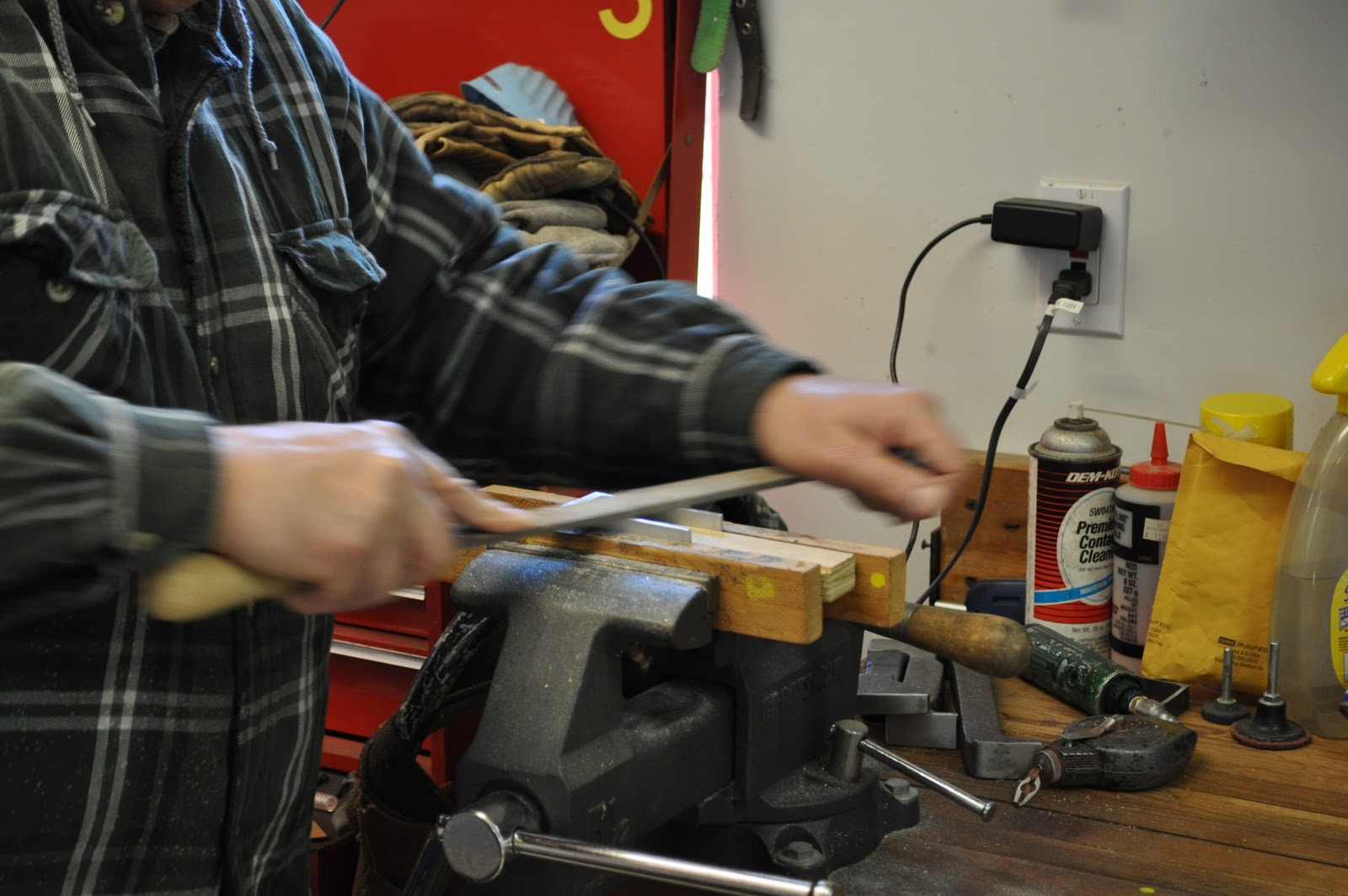
I made a quick call to Mustang Aero and told Chris Tieman of my dilemma.  Chris told me to clamp a pipe onto the aluminum angle so as not to kink it.  After talking to Chris I was full of confidence again.  I removed the right upper stringer from the plane and laid it on my flat work bench.  Yup!  It needed to be bent.    

The shot at right is after I bent the stringer 3" and removed most of the clamps.

I strapped a 1/2" electrical conduit right up to where station 99.35 bulkhead would be.  I secured the remainder of the aluminum angle to the bench.

The conduit held the angle in place so it wouldn't kink.  Worked pretty good.

Here is another shot of the setup after I bent the angle.

I clamped the angle back on the right side of the plane and it looked good.  Nice symmetrical fit with the left side stringer.

This is how it goes some times.  Testing & fitting parts together multiple times to get the best fit prior to final assembly.  This process is repeated several times for each piece.

If you are a little off in a measurement or proper fit by the time you get the other parts together you'll end up way off.  So, lots of double and triple checking.  Each day a little more progress.

Tomorrow, I will work on the firewall and try and have it clamped to the forward fuselage side skins by the end of the weekend.  I have to keep going.

Later,
Brian