Sunday, January 29, 2012

Forward Fuselage (8th Incident)

Still working the forward fuselage.
There is a lot happening in the front of the aircraft.

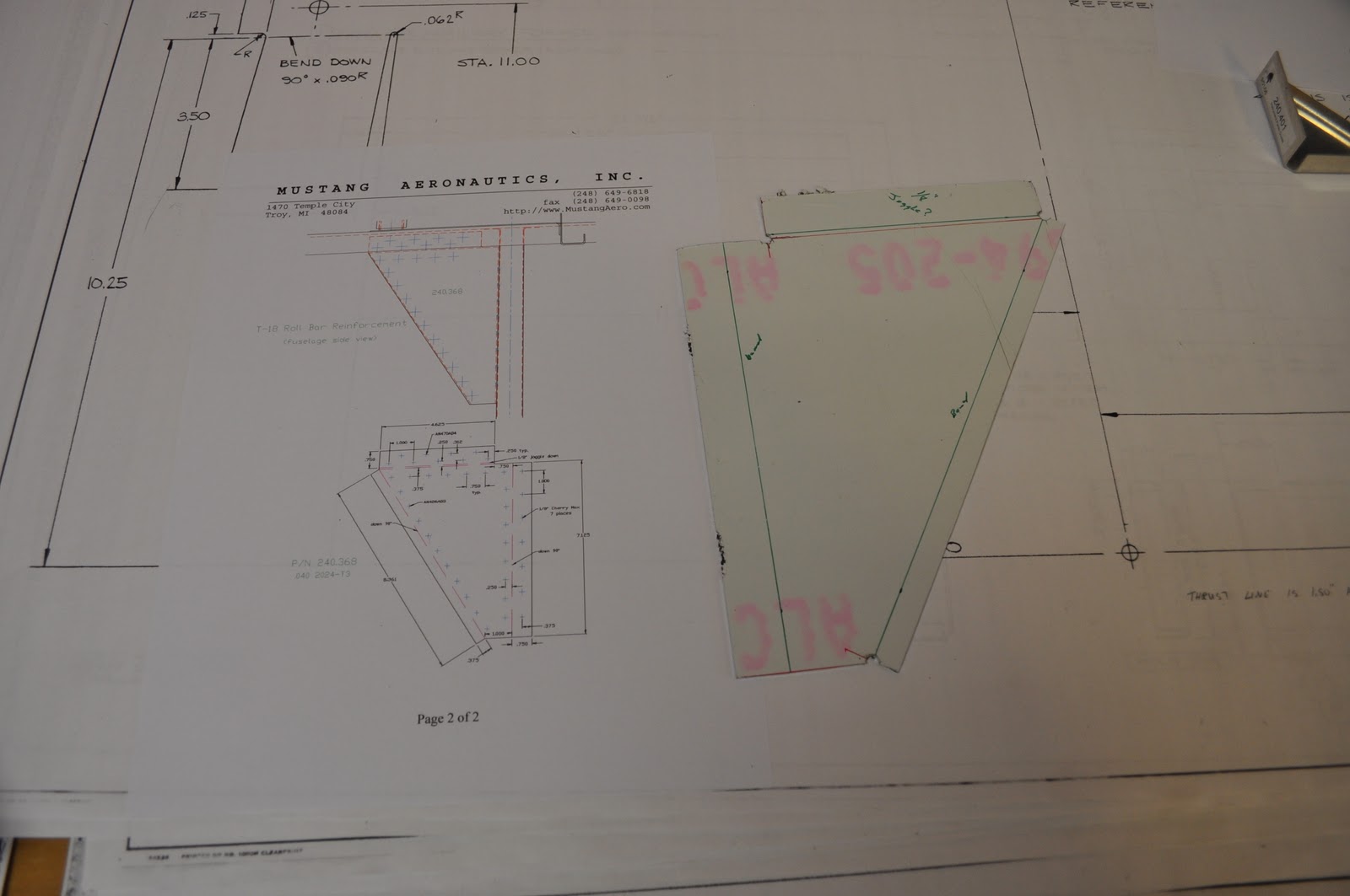
The brackets the engine mount bolts to are similar, but different then the Cessna brackets.  The plans call for 7 rivets on each side of the bracket for a total of 14 rivets.  It looked a little light duty for holding an engine on the front of the plane.

The Cessna brackets are triangular while the ones supplied by M-Aero are more rectangular.

Being rectangular and with the amount of overlap on the forward fuselage side channels, I was able to get 9 rivets per side.

That's 4 rivets more per channel.

A slight increase on weight, but more structural support for the engine.

The lower forward fuselage channels that support the floor were another story.  The prints called for 7 rivets on each side as before.  (14 total.)  The big difference is the design of the channel.

It is more like a squared off "U" and the bracket fits inside of the channel.  One side of the bracket has total surface contact with the channel.  The other side has about 2/3 contact with the channel.

That means less riveting area.


I was able to get 5 rivets nicely spaced on the 2/3 contacted side and 10 on the full contact wide.  (15 total.)

One thing I need to figure out is what to do with the firewall.  On the bottom of the firewall, where the forward tunnel area is, there are two wings of material that bend into the tunnel area.

Before I rivet the engine mount brackets on to the channels, I have to find whether the firewall wings rivet to the side channels.

Enough for this weekend.

Brian

Sunday, January 15, 2012

Forward Fuselage (Chapter 7)

The saga of the forward fuselage construction continues.  You put the parts on, mark them, and then you remove them.  Trim, trim, trim, cut, cut, cut, file, file, file, fit fit fit........

It does get a little tedious and annoying.  I want to make progress and get flying while I am still on this planet.

But, as with all things worth waiting for, it takes time and patience to construct an airplane.  Let's face it.  If it were easy everyone would be doing it.  

So after numerous times on and off I had marked up the front side skins and decided to start hanging some more parts.

There are lots of skin stiffeners, so I got to measuring and cutting some of the material to fit in the cockpit area.

I squared everything up with the HRL and bulkheads.  They fit pretty good.

Here is the forward skin clamped to the side of the plane.  Prior to putting the skin back in place I used a number 41 drill and match drilled the skin.

I clamped the pre-drilled skin in place and squared it to my reference lines.
Here is the right side skin in Cleco-ed in place.  Once I had the skin clamped in place I drilled the number 41 holes out to a number 40 size and Clecoed every hole as I went.

When the was done I went over the skin with a Sharpie marker and marked it all up to what size rivets go where.  Next I drilled the number 40 holes out to number 30 where needed.

Here I am doing to the left side as I had previously done to the right.  Being sure my drill is perpendicular to the skin and angle aluminum.  Baby steps.
 After all the drilling I assembled up the forward fuselage again.  Mounted the firewall, cockpit floor structure, and side channels.

In the rear area I put in the baggage floor, control tunnel, and the station 114.75 bulkhead.

Now it is starting to look like something.  CL and HRL are lining up to easy.  I start to think I may be missing something.
So, there she is.  Half Cleco-ed and half clamped.  Next time I will try and get the motor mounts
drilled to the various forward channels.  It is still going together slow, but that's why they say
slow and steady wins the race.  You just have to keep at it.
Brian

Friday, January 13, 2012

Forward Fuselage ( Continued, 6th Edition.)

Part of the forward fuselage construction is the T-18 Roll Bar.  It consists of the roll bar, mounts for the roll bar and diagonal braces just below the roll bar.

The aluminum for the diagonal braces comes stamped out.  You, the builder, get to enjoy bending a couple of 90 degree angles on two sides and a "joggle" on the third side.

The "joggle" is made in the piece to fit behind the upper fuselage 1" X 1" X 1/8" aluminum angle.

There is a left & right brace to build.

I marked lay-out lines on the supplied parts then tried to figure out the best way to bend an 1/8th inch "joggle".

I wrote the Yahoo Mustang II builders group and asked, how to?  I received a lot of good answers.  The one I went with seemed to work pretty well.  (See picture at right.)


For small bends in the aluminum, the vise and a plastic mallet work great.

To keep from marring the aluminum, I use a pair of wood blocks.  The wood blocks take a beating from the teeth on the vise and not the aluminum.

Here I have made my 90 degree bend and I am about to make the "joggle".  I bent the other 90 degree angles in the same manner.


I test fitted the assembly to the fuselage.  Looked pretty good.

I made numerous adjustments with a hammer to get a nice tight fit.

Now, I am running low on copper Clecos.  (1/8th inch.)  May need to borrow some.


Well, the sun goes down on another day of experimental aircraft construction.  I have so much more to complete.  I am striving to get this thing on the gear by this summer.

I'll give it my best shot!

Later,

Brian

Thursday, January 12, 2012

Forward Fuselage (Continued 5th installment.)

December was a busy month.  No real time applied to building.

Started the new year test fitting the firewall to the front of the airplane.  Clamped the whole assembly together with "C" clamps and aligned it to the center line I struck on the floor a few months ago.

I  marked the center line and the Horizontal Reference Line (HRL) on the firewall and the forward bulk heads.


I found plumbing the center line to the mark on the floor was easy.  Trying to find the HRL was starting to be difficult.  How do you find a line that is out in the middle of no where?

I tried stretching a taught string,  but there is no place to tie it off.  So, I was in a dilemma on how to locate the HRL, consistently, during the assembly of the fuselage.

I have one of those lasers used to hang pictures and stuff on the walls of the house.  It shoots a line around the room.  It can hit 2 or 3 walls.

I set it up on a camera tripod to try out.  It proved to be too dim to see and was very inaccurate.  I could not get any repeatability from the laser.

I priced out getting a cheap tripod with spinning laser.  Nothing under a few hundred dollars.

I found that the digital level I bought has a laser.  I mounted it to the camera tripod and with several attempts at leveling the laser in two planes I found if I was careful I could find the HRL with some accuracy.

The attached picture shows the  red laser going through the hole for the HRL in Station 99.35 and shining on the HRL line I drew on Station 73.75.

Looking pretty good to me.  When I swivel the tripod, the laser follows the HRL around the structure.

I will try this for a while and try and build my trust with it.  Before I get to much further along I will check the CS for being level in the fixture again.  Just to make sure it hasn't moved prior to moving on in the assembly of the fuselage.

Later,
BWW

Sunday, January 1, 2012

Happy New Year!

December 2011 was quite busy.  Now it is a new year and I have a plane to build.  Should be able to get back at it this week.

I wish everyone a great safe new year in 2012!

Brian W.