The instruction book says to put the wing in a fixture. Level it end to end using the top of the main spar. Then level it from the leading edge to trailing edge using the wing reference line (WRL). After all that, drop a center fuselage line down from the center section to the floor and draw a nice straight line.
Well, I did a lot of lay out work over the years and I did this a little different. I cleared the floor space I needed to construct the fuselage and made a nice straight line. I did this by stretching a nylon string really tight and touching the floor of the garage. I checked my measurements a couple of times to ensure there was indeed enough room to continue construction. I sprayed paint over the string to mark the floor.
The line was very faint so, I took a straight edge and marked it with a Sharpie pen. To make sure it was straight I through a laser on it. Looks good!
The bottom of the frame is 1 1/2 inch angle iron. My friend Tom R. let me come over and use his welder to weld the angle into a rectangle. (Thanks Tom!) Before going to Tom's I had prepped the steel work by drilling holes for mounting brackets and bolting to the concrete floor.
The up rights that the main spar is attached to are made from clear pine 1x4 seasoned in my garage for just such a project. It also has some 3/4 sanded plywood laminated to it for strength and anti warpage.
I pulled everything square to put the uprights in an outward tension when the wing was placed on them. Tied the up rights together with cross bracing. The outside dimension front to back is about 26". This would place the wing mounting brackets around the 1x4 pine.
When all was ready Scott S. came over to help me lift the wing out of the vertical fixture I used to assemble the wing in. (Thanks Scott!) Hey, this thing is pretty light. I wonder if it will fly?......
The CS wing fit like a glove in the new fixture. Lots of room to work around and under it.
I had the fuselage center line located on the CS wing and the CS wing in the fixture. Now I had to locate the wing's center line over the line on the floor. I dropped a plume line down from the line marked on the CS wing to the floor and gently moved the fixture to align the plume bob with the line on the floor.
A little on the trailing edge, a little more on the front.....there we go. I checked for squareness at station 73.75. ( I made marks on the floor for each fuselage station for reference purposes.)
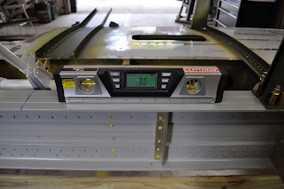
After aligning the CS wing to the floor marks I drilled into the floor and anchored the fixture to the floor with Red Head concrete wedge bolts. Prior to tightening I leveled the CS wing and fixture. Double zero on the main spar.
The WRL is a different story. It is off by .7 degrees. The top skin trailing edge pivots up at the last rivet row. I will need to consult with the online builders group to get suggestions and ideas on how best to adjust this. I seem to remember a thread that spoke of a problem like this. The builder just simply used a large mallet to shape it the way it needed to go.
So, there she is ready for the forward fuselage. I will start that this next weekend.
Later,
Brian


No comments:
Post a Comment