Tuesday, October 4, 2011

Riveting the Bottom Skin

Riveting the bottom skin takes a little planning and some help from a fellow builder. My arms are not long enough to hold the pneumatic rivet gun and the bucking bar.

I rigged the skin so I could reach underneath in some of the areas. There were also some access holes on the top side to reach through. Still it was fun.

We started at the main spar and worked our way to the trailing edge.


Looking up at the main spar joint. Used a few cushions to raise myself up to a comfortable position. I still had to reach all the way up to the spar.
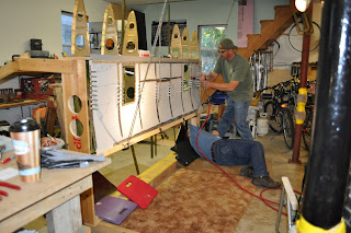


I'm on the floor with the bucking bar and Dan H. is on the gun. If you get a good rhythm and timing thing going, the riveting goes pretty good.

The 1/8" rivets in the main spar were a little harder to drive. A few more "beats" on the hammer then on the 3/32" rivets. The 3/32" rivets held a majority of the skin to the bottom rib structure.


It sure helped to have those under seat storage holes! For most of the center of the center wing section I was able to reach through some type of access hole. A lot easier then lying on the floor and reaching up.

My florescent drop light fit right in to add a little light to the situation.


Here I am at the trailing edge of the center wing section. I'm using the main squeeze to set the last row of 1/8" rivets. I know some of the builders prefer a pneumatic squeezer, but for the few rivets needed to be squeezed this is pretty easy.


Next step is to get some iron welded up to make a fixture to hold the center section flat and level. Then I'll be able to start on the forward fuselage structure.

Later,
BWW


Tuesday, September 13, 2011

Bad Rivets

I thought this would be a good topic.

After squeezing a multitude of rivets yesterday, I found a few rivets that I really didn't like. The shop heads were off-set to one side. Not very good. So, today I removed these rivets and replaced them.

All toll, there were four rivets to be removed and replaced.


Two rivets drilled out and two to go!

I marked the heads of the rivets to be removed with a Sharpie pen. Notice the deformation of the aluminum shear web. This was my first clue there might be a problem prior to flipping the part over.

The goal is to drill out the rivet to remove the factory head. Then punch the rest through the aluminum parts. You do not want to damage anything. That would mean more work.

Here are the remains of the rivets after removal.

Crap! Look at the off-set in these rivets. The stem of the rivet is even damaged. This is why each and every rivet needs to be inspected.

Using the rivet gauge and looking at each one insures a well built aircraft. One you would like to fly in.

Long story short. Practice riveting. Practicing does not guarantee good rivets every time. Inspect every rivet! Get good at removals. You'll be doing a few over the years of building.

A little touch up primer and it's good as new.

Later,
BWW

Monday, September 12, 2011

More on Fuse Formers

Over the weekend I didn't have a lot of free time due to various things. I did find time to start riveting the fuselage formers I started last month.

This is a shot of fuselage station former 162.00. The former is six pieces of aluminum. Four for the top, bottom, & sides with two shear webs riveted to the bottom corners for strength.


This is very similar to constructing a large RC plane. Only it would be constructed of plywood & epoxy resin.

I built and wrecked a lot of RC Planes in the 90s. Maybe some time I will up load the spiral of death my P-47 kind of survived.

Here's a shot of the rivet shop heads I made with the main squeeze. Nice and uniformed.

This former needs a little touch up primer and a few drilling guide holes for the skins and it will be all set.

Assembling the formers has been one of those busy tasks that has to be completed. When I can not progress on the main plane, because I lack the extra hand I need to complete that riveting, I look into the plans for subassemblies.

Keeping the idea of getting ahead by completing subassemblies I started laying out the fire wall.

The fire wall is made up of some very light gauge stainless steel. To beef it up some aluminum angles are riveted to the front and back side of it.

The front side of the fire wall gets a couple of aluminum angles attached to it looking like a "T".


The back side gets a couple of more aluminum angles. There are a few more parts that go on the fire wall (like an engine) that I have to locate in the many boxes of parts I got from Mustang Aero. (I hope it's in here some place.)

You can faintly see in the last picture the many layout lines I scribed, I mean drew with a Sharpie pen. I like lots of colors.

The Horizontal Reference Line (HRL) is in red & the Center Line (CL) is in blue.

I aligned the aluminum angles with #40 holes for now. I will drill them out to #30 at a later date. (Like when I have an engine...It's got to be in one of these boxes.....)

Well, I'm hoping to get more done this next weekend. Only time will tell. BWW


Sunday, August 28, 2011

EAA Tech Support & More Formers

On Friday evening I had a visit from an EAA Technical Counselor. It was his initial visit. Having an EAA Tech Counselor come over helps to insure you understand what you are doing. They offer guidance, tips, help from other builders, and good moral mental support for those tough decisions you are going to have to make during the project.

Well, the Tech Counselor said the riveting looked pretty good and the project was well on it's way. The rivets looked pretty good because I had help from my significant other, Christine.

Here's a shot of Christine using a 3X pneumatic rivet gun. She did a great job. Thanks Chrissy!

Christine had no problem with the universal head rivets. The flush head rivets are another story. They are tough.


Here are the parts for the last fuselage former assembly. They end up connecting to the last two formers on the fuselage, stations 205 & 209. I can't remember the station number for the life of me, but I think it is 194.609.

The vertical fin and the horizontal stabilizers connect to this former and the last two. Again, and I can not stress this enough, look over the prints very carefully. The details of how the assembly goes together are there. You just have to look at all the prints. (Several times.)

This is the aft end of the aircraft. The tail wheel mounts on the last two formers, the smaller two. It bolts onto the bottom of them.

I still have to install the brackets for the vertical stabilizer, nut plates, debur, counter sink & dimple on some areas, and corrosion protect each part of the assembly. Then finally rivet together.

I will complete the riveting when I build the fuselage assembly. That will occur after the bottom skin is installed on the center section & the CS is in the jig for assembling the fuselage. Ugh! More work to do.

Later,
Brian


Saturday, August 27, 2011

Fuselage Formers

The months of June and July went by fast. We had two summer storms that knocked out power to my father-in-law twice in a two week period. It didn't help his failing health and it took up most of our time. He is doing better for now, but we don't know how long he will be this good. We take it day by day.

Now let's talk about the Mustang II. Well, while waiting for the EAA Tech Counselor this last week, I went fuselage former crazy!

I was able to drill, debur, corrosion protect, and assemble most of the fuse formers. Each former has about 6 to 8 hours in it depending on how complex it was.

So, from bottom to top they are fuselage station formers, 114.75, 138.0, 162.0, & 187.5. These were all fairly straight forward. Most of the rivet holes were matched drilled & the parts were nicely formed. I completed these formers in about 6 days. 114.75 took about a day and a half. The zinc chromate (green) ones with the corner shear webs, I ended up making my own webs for. The ones from MII were a bit to small & the rivet holes ended up too close to the edge. (Not good!)

These are formers 205 & 209. This assembly is made up of about eight parts. Lots of measuring, locating the parts and where they go. The tail wheel & horizontal stabilizer attache to this assembly.

There is a very specific order of operations when assembling multiple parts like this. Any missed step and you can damage a part and make it useless.

Then you have to improvise.

My case in point. This is part #250.357, front fin spar doubler. The one on the left is from MII. I cut the large slot the elevator push rod passes through then I tried to bend the edges up 90 degrees. As you can see the part was a miserable failure.

The part on the right I cut from flat stock, bent the edges, cut the slot, then I used the plywood cut out and a hammer to shape the flange. It came out perfect. (Just needs a little adjusting.)

Tomorrow I hope to work on station 194.609. It attaches to the 205/209 assembly. According to the prints it looks like fun!

Next post I'll write about the EAA Tech Counselor visit.

Later,
Brain

Wednesday, May 18, 2011

Getting back in the game

For the last three weeks I did not do any building on the plane. Yesterday, I started to get back in the game. Trying to figure out where I left off and what needed to be accomplished next. What a pain!

After cleaning all the saw dust up from the garage, I worked on getting reacquainted with the lower fuselage stringers and the baggage compartment on Tuesday. I called Mustang Aero for more information on the stringer locations. Then I drilled the holes & de-burred.

Today, I started assembling 240.3310 and 240.33111,left and right sides, which are two bulkheads that will attach to station 73.75 on the main spar.
The two sides of each bulkhead are riveted together and to aluminum angles which will be bolted to the main spar with six AN3-6A bolts.

I need to get all of this completed so I can rivet on the bottom skin which will allow me to move to a different phase of building. That would be building the fuselage.


That moves me into more of the aircraft controls. I have a lot of planning I need to think ahead too. I'd really like an auto pilot. So, I need to think about servos and their instillation.

While at Mustang Aero in March I took a look at Chris Tieman's MII aileron servo installation. It is located in the center section wing. (See Picture at right.)

I will also need a servo for pitch control. Not real sure where to turn for better info. I'm still investigating options at this point, but need to figure something out so I can buy and mount the servos properly.

Here is a picture of one of my quick build wet wings at Mustang Aero. Chris will be delivering it to me on his way to Oshkosh in July.

I have to make a wing holder for both wings so I can safely store them while I finish the plane. I have some old machinery lifting straps that will do just great. I just have to make some kind of frame.

Tomorrow, I will be back at work for a few days. Should be able to get my head wrapped around the project on Monday. I need to order a few hardware parts from Wicks Aircraft so I have enough rivets to finish the center wing section.

I hope everyone has a great safe week!

Brian


Saturday, May 14, 2011

A Sod Event

Ok, this has nothing to do with building an airplane, but it has everything to do with my time. (Honey do things.)

It started with trying to get the back yard to green up this spring. I ended up putting down 3600 square feet of sod.

We started by roto-tilling part of the back yard. In the end we did the whole thing.


I also ordered 5 yards of soil to fill in the low spots. We didn't get enough soil. We made do.

I probably should have ordered a few more yards of dirt. After we were done, I thought about a sprinkler system since we were watering daily.


The sod company starts cutting sod at the farm at 4 AM. The delivery was suppose to be by 6:30 AM. They didn't arrive until 9 AM. Lots of wasted time waiting.

The big tree's roots were sticking up out of the ground. Instead of covering them with soil and sod I built a free floating deck over them. It is in the shape of an Octagon. It looks pretty good.


So, we got a late start laying the sod. We still had it all down by 3 PM.

There I am watering the green. That was last weekend. This weekend I have been trying to put the deck on the Octagon.

Instead of just putting decking down what do I do? I choose to cut all the decking in the many octagon angles. 22.5, 67.5, and lots of 45 degree cuts. How fun......


Should be done with the project just in time to go back to work.

I'll get back to the build some day...........Brian