Sunday, October 30, 2011

Start of Forward Fuselage

I finally leveled the CS wing in the fixture.  Looking pretty good.  Now I have the next phase of the build ahead.  Constructing the forward fuselage.  I clamped the upper fuselage stringers in place and removed the CS leading edges.
Next, I test fitted the forward fuselage side skins.  Had to make some rough cuts to adjust the fit.  The skins came pre shaped and marked up.  I measured and marked again just to be sure before I cut any metal.
 Here the skins are roughed in and clamped.  Before I can go any further I need to complete construction of the fire wall.
Side skins in place.  I will probably need to take the skins on and off a few times before calling this complete.  Lots to contemplate over the next week.

Later,
Brian

Wednesday, October 26, 2011

Building the fixture

The instruction book says to put the wing in a fixture.  Level it end to end using the top of the main spar.  Then level it from the leading edge to trailing edge using the wing reference line (WRL).  After all that, drop a center fuselage line down from the center section to the floor and draw a nice straight line.
Well, I did a lot of lay out work over the years and I did this a little different.  I cleared the floor space I needed to construct the fuselage and made a nice straight line.  I did this by stretching a nylon string really tight and touching the floor of the garage.  I checked my measurements a couple of times to ensure there was indeed enough room to continue construction.  I sprayed paint over the string to mark the floor.

The line was very faint so, I took a straight edge and marked it with a Sharpie pen.  To make sure it was straight I through a laser on it.  Looks good!
The bottom of the frame is 1 1/2 inch angle iron.  My friend Tom R. let me come over and use his welder to weld the angle into a rectangle.  (Thanks Tom!)  Before going to Tom's I had prepped the steel work by drilling holes for mounting brackets and bolting to the concrete floor.

The up rights that the main spar is attached to are made from clear pine 1x4 seasoned in my garage for just such a project.  It also has some 3/4 sanded plywood laminated to it for strength and anti warpage.  
I pulled everything square to put the uprights in an outward tension when the wing was placed on them. Tied the up rights together with cross bracing.  The outside dimension front to back is about 26".  This would place the wing mounting brackets around the 1x4 pine.
When all was ready Scott S. came over to help me lift the wing out of the vertical fixture I used to assemble the wing in.  (Thanks Scott!)  Hey, this thing is pretty light.  I wonder if it will fly?......
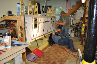
The CS wing fit like a glove in the new fixture.  Lots of room to work around and under it.

I had the fuselage center line located on the CS wing and the CS wing in the fixture.  Now I had to locate the wing's center line over the line on the floor.  I dropped a plume line down  from the line marked on the CS wing to the floor and gently moved the fixture to align the plume bob with the line on the floor. 

A little on the trailing edge, a little more on the front.....there we go.  I checked for squareness at station 73.75.  ( I made marks on the floor for each fuselage station for reference purposes.)
After aligning the CS wing to the floor marks I drilled into the floor and anchored the fixture to the floor with Red Head concrete wedge bolts.  Prior to tightening I leveled the CS wing and fixture.  Double zero on the main spar.

The WRL is a different story.  It is off by .7 degrees.  The top skin trailing edge pivots up at the last rivet row.  I will need to consult with the online builders group to get suggestions and ideas on how best  to adjust this.  I seem to remember a thread that spoke of a problem like this.  The builder just simply used a large mallet to shape it the way it needed to go.
So, there she is ready for the forward fuselage.  I will start that this next weekend.

Later,
Brian

Tuesday, October 25, 2011

Center Section Wing Is In The Fixture!


Hey, this is a blog site so I am going to rant on building a little bit.

First, it is a big decision to build just a bout anything. A house, car, boat, whatever. It starts with the first steps. Dreaming, investigating, brochures, and planning. Lot's of it. Building an airplane is no different.

I've had the aviation bug going back to my earliest memories. My mom nourished those thoughts by giving me aviation books and models.  (Still have the books.)  My dad was in the Army Air Corp during WWII. He was an armament specialist on P-47 Thunderbolts. Thanks Mom & Dad for everything!

My first General Aviation (GA) plane I bought was in one of those same books my mom got me in the 60's and early 70's.  (How to Buy a Plane.)  It took me until 2002 to really answer my call to aviation. I received my private pilots certificate on December 8, 2003, just before the 100th Anniversary of flight.

I purchased the flap kit for the Mustang II from Mustang Aeronautics in March of 2010. It was delivered in early April and I went on to complete it in June 2010.

There are quite a few things I learned about building from the flap assembly. Building will be hard at times. Building can be tedious. The smallest parts & tasks can (and usually do) take the longest to complete. But, on the other hand, building can and is rewarding and most importantly I can do this. I can do this! AND, so can you.

I have acquired some of the necessary skills needed to build a plane just by completing the flap kit. I also called Chris, at Mustang Aero with questions. (Chris is a wealth of information on the plane.) I joined the on line builders group, mustangaero, on Yahoo. I have been an EAA member since 2001 and have been a member of a local EAA chapter since 2010. (Not to mention all the building airplanes books and literature I have accumulated over the last couple of decades.)

All of that in the above paragraph helps to keep me on a track to complete my airplane. Everybody or group mentioned wants you to complete your dream. Some of those individuals will go out of their way to see that you are progressing to completion. This network of people is a great resource.

If you decide to build you will need your family's understanding and support. Without it you will not be able to complete the project or enjoy what you are doing. (You need some understanding also. You have to make time for the family , too.)

In October of last year I ordered the remainder of the plane. I received the plans and building instructions right away. I picked the plane up from Troy, Michigan, home of Mustang Aeronautics, on March 29, 2011. I started building right out of the box.

I found at times it was hard to find time to build. All kinds of other stuff just kept getting in the way. (Life)

If I get away from the project for a few days it takes me a day or two to get back in the swing or to find where I left off. So, plan, investigate, trim and fit, drill and debur, put together, take apart, try again.........and finally you get to a point where you feel you have accomplished something.

Maybe you achieve one of the small goals or a milestone in the building process that makes you feel like you have accomplished a major goal in your building timeline that really makes you feel you are going to build and fly this airplane in your lifetime!

With the help of several friends over the last weekend I feel I have crossed a point in the building of my plane that has made me feel very good and I have to say thank you for all of your help! Without it I would not be as far along as I am.

There you go! The wing center section is complete and on a new assembly fixture. I will now start assembly of the forward fuselage and back to the empennage. My next goal is to have the airplane on the "gear" by the summer of 2012.

It will happen as long as I keep trying to do a little each day. Planing & dreaming!

Later,
Brian


Tuesday, October 4, 2011

Riveting the Bottom Skin

Riveting the bottom skin takes a little planning and some help from a fellow builder. My arms are not long enough to hold the pneumatic rivet gun and the bucking bar.

I rigged the skin so I could reach underneath in some of the areas. There were also some access holes on the top side to reach through. Still it was fun.

We started at the main spar and worked our way to the trailing edge.


Looking up at the main spar joint. Used a few cushions to raise myself up to a comfortable position. I still had to reach all the way up to the spar.


I'm on the floor with the bucking bar and Dan H. is on the gun. If you get a good rhythm and timing thing going, the riveting goes pretty good.

The 1/8" rivets in the main spar were a little harder to drive. A few more "beats" on the hammer then on the 3/32" rivets. The 3/32" rivets held a majority of the skin to the bottom rib structure.


It sure helped to have those under seat storage holes! For most of the center of the center wing section I was able to reach through some type of access hole. A lot easier then lying on the floor and reaching up.

My florescent drop light fit right in to add a little light to the situation.


Here I am at the trailing edge of the center wing section. I'm using the main squeeze to set the last row of 1/8" rivets. I know some of the builders prefer a pneumatic squeezer, but for the few rivets needed to be squeezed this is pretty easy.


Next step is to get some iron welded up to make a fixture to hold the center section flat and level. Then I'll be able to start on the forward fuselage structure.

Later,
BWW


Tuesday, September 13, 2011

Bad Rivets

I thought this would be a good topic.

After squeezing a multitude of rivets yesterday, I found a few rivets that I really didn't like. The shop heads were off-set to one side. Not very good. So, today I removed these rivets and replaced them.

All toll, there were four rivets to be removed and replaced.


Two rivets drilled out and two to go!

I marked the heads of the rivets to be removed with a Sharpie pen. Notice the deformation of the aluminum shear web. This was my first clue there might be a problem prior to flipping the part over.

The goal is to drill out the rivet to remove the factory head. Then punch the rest through the aluminum parts. You do not want to damage anything. That would mean more work.

Here are the remains of the rivets after removal.

Crap! Look at the off-set in these rivets. The stem of the rivet is even damaged. This is why each and every rivet needs to be inspected.

Using the rivet gauge and looking at each one insures a well built aircraft. One you would like to fly in.

Long story short. Practice riveting. Practicing does not guarantee good rivets every time. Inspect every rivet! Get good at removals. You'll be doing a few over the years of building.

A little touch up primer and it's good as new.

Later,
BWW

Monday, September 12, 2011

More on Fuse Formers

Over the weekend I didn't have a lot of free time due to various things. I did find time to start riveting the fuselage formers I started last month.

This is a shot of fuselage station former 162.00. The former is six pieces of aluminum. Four for the top, bottom, & sides with two shear webs riveted to the bottom corners for strength.


This is very similar to constructing a large RC plane. Only it would be constructed of plywood & epoxy resin.

I built and wrecked a lot of RC Planes in the 90s. Maybe some time I will up load the spiral of death my P-47 kind of survived.

Here's a shot of the rivet shop heads I made with the main squeeze. Nice and uniformed.

This former needs a little touch up primer and a few drilling guide holes for the skins and it will be all set.

Assembling the formers has been one of those busy tasks that has to be completed. When I can not progress on the main plane, because I lack the extra hand I need to complete that riveting, I look into the plans for subassemblies.

Keeping the idea of getting ahead by completing subassemblies I started laying out the fire wall.

The fire wall is made up of some very light gauge stainless steel. To beef it up some aluminum angles are riveted to the front and back side of it.

The front side of the fire wall gets a couple of aluminum angles attached to it looking like a "T".


The back side gets a couple of more aluminum angles. There are a few more parts that go on the fire wall (like an engine) that I have to locate in the many boxes of parts I got from Mustang Aero. (I hope it's in here some place.)

You can faintly see in the last picture the many layout lines I scribed, I mean drew with a Sharpie pen. I like lots of colors.

The Horizontal Reference Line (HRL) is in red & the Center Line (CL) is in blue.

I aligned the aluminum angles with #40 holes for now. I will drill them out to #30 at a later date. (Like when I have an engine...It's got to be in one of these boxes.....)

Well, I'm hoping to get more done this next weekend. Only time will tell. BWW


Sunday, August 28, 2011

EAA Tech Support & More Formers

On Friday evening I had a visit from an EAA Technical Counselor. It was his initial visit. Having an EAA Tech Counselor come over helps to insure you understand what you are doing. They offer guidance, tips, help from other builders, and good moral mental support for those tough decisions you are going to have to make during the project.

Well, the Tech Counselor said the riveting looked pretty good and the project was well on it's way. The rivets looked pretty good because I had help from my significant other, Christine.

Here's a shot of Christine using a 3X pneumatic rivet gun. She did a great job. Thanks Chrissy!

Christine had no problem with the universal head rivets. The flush head rivets are another story. They are tough.


Here are the parts for the last fuselage former assembly. They end up connecting to the last two formers on the fuselage, stations 205 & 209. I can't remember the station number for the life of me, but I think it is 194.609.

The vertical fin and the horizontal stabilizers connect to this former and the last two. Again, and I can not stress this enough, look over the prints very carefully. The details of how the assembly goes together are there. You just have to look at all the prints. (Several times.)

This is the aft end of the aircraft. The tail wheel mounts on the last two formers, the smaller two. It bolts onto the bottom of them.

I still have to install the brackets for the vertical stabilizer, nut plates, debur, counter sink & dimple on some areas, and corrosion protect each part of the assembly. Then finally rivet together.

I will complete the riveting when I build the fuselage assembly. That will occur after the bottom skin is installed on the center section & the CS is in the jig for assembling the fuselage. Ugh! More work to do.

Later,
Brian