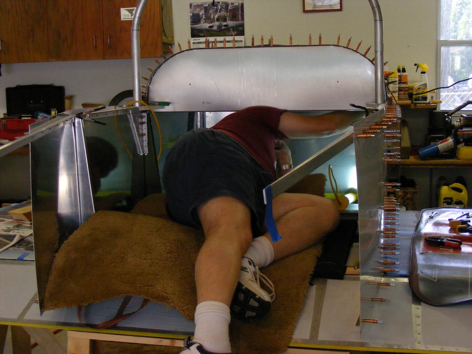
The instructions say to build the tail cone on the airframe and on a table/work surface. I had some left over plywood from the MII kit and built a work surface today.
My big question was what is the angle from station 114.75 to 209.5? How many degrees? As near as I could tell from the plans it is approximately 4 degrees. So, I picked this as a starting point.
The work surface is about 4 degrees. It may be a little steep.
I braced it for my weight when I get inside for riveting at a later date. It will be anchored to the floor with some Hilti concrete bolts on the center line when all is good.
Test clamped the 209.5 and 205 bulkheads to the work surface. Tomorrow I will setup the spinning laser and see if the HRL lines up. Could be an interesting day.
I made a doubler for the tail end to support the landing gear and a heavy landing. I only hope the work surface lines up OK with the HRL.
Later,
Brian W.
This site will be dedicated to my latest aviation project. I will be investing my time and money into building an all metal aircraft. The Mustang II.
Saturday, August 11, 2012
Tuesday, August 7, 2012
Rear Bulkheads
This last weekend I started sizing up building the epinage section. Last fall I assembled and riveted most of the bulkheads. Stations 205 & 209 I drilled and Clecoed together until now.
The first step is to mount the vertical stabilizer spar for the rudder to bulkhead 209.
BLARG!!! The three holes I drilled last fall do not line up with the factory assembled spar! Not the factories fault. It is mine. (Old bulkhead at right.)
I missed two of the holes by about 1/6th inch. I could just drill them out to the next size, but that wouldn't be right. So, I found some .032 aluminum stock and made a new 209 bulkhead.
Here is my home made bulkhead. The bending brake came in handy. I used the factory assembled spar to "match" drill the holes in my new bulkhead.
Corrosion protected and riveted the bulkhead looks pretty good. I need to mark the CL and HRL on the bulkhead.
I corrosion protected and riveted up the 205 bulkhead and the adjoining parts.
This made for a full weekend. I will have to start making the assembly "table" for the epinage section so I can start assembling from bulkhead station114.75 to bulkhead station 209.
Still have to get my wings from the factory. They are having an open house August 18th & 19th. I may go that weekend.
More to come......
BWW
The first step is to mount the vertical stabilizer spar for the rudder to bulkhead 209.
BLARG!!! The three holes I drilled last fall do not line up with the factory assembled spar! Not the factories fault. It is mine. (Old bulkhead at right.)
I missed two of the holes by about 1/6th inch. I could just drill them out to the next size, but that wouldn't be right. So, I found some .032 aluminum stock and made a new 209 bulkhead.
Here is my home made bulkhead. The bending brake came in handy. I used the factory assembled spar to "match" drill the holes in my new bulkhead.
Corrosion protected and riveted the bulkhead looks pretty good. I need to mark the CL and HRL on the bulkhead.
I corrosion protected and riveted up the 205 bulkhead and the adjoining parts.
This made for a full weekend. I will have to start making the assembly "table" for the epinage section so I can start assembling from bulkhead station114.75 to bulkhead station 209.
Still have to get my wings from the factory. They are having an open house August 18th & 19th. I may go that weekend.
More to come......
BWW
Thursday, August 2, 2012
Station 114.75 In Place
After clamping I drilled 1/8th inch holes for rivets. Some of the bulkheads come from Mustang Aeronautics with pilot holes drilled in them.
So, I started drilling from the inside out. I used a #40 drill going from the inside out making my own pilot holes in the skin. Clecoed the assembly up with the silver Clecos.
Next, I drilled from the outside in using an 1/8th inch drill, or a #30. On the way in, I made sure the drill was perpendicular to the skin to get a nice straight hole through the structure. Looks pretty good.
I have decided for now to go with the bench seat. If I don't like it, I will change it out to something else later.
The bench seat requires a right and left seat attachment bracket, 280.302. You have to find some scrap .040 aluminum to make these yourself. Sounded like an opportunity to use the new 30" brake.
I cut two pieces of aluminum 4" by 7" nice and square. Marked it up for bending and bent away in the brake. The first two bends went great. The third bend I could not do in the brake due to its location. BLARG!!! I bent it in the vice.
They came came out pretty good. When I went to mount them in the aircraft something didn't look right. I couldn't quite put my finger on it right away. I had placed the right on the left and the left on the right! I was fortunate though. I had made them so well I was able to move them and Cleco them into their correct positions.
Pilot side.....
And the passenger side.
Not bad for a couple of hours.
I am getting close to calling the EAA Technical Councilor for another inspection.
I will try and figure out how to do the tail cone this weekend. I have all the bulkheads made up. That should help to speed things along once I get going.
BWW
Wednesday, August 1, 2012
360 Degree Spinning Laser
I have been relying on measurements from various locations to keep the fuselage assembly running true to the Horizontal Reference Line (HRL). The Center line (CL) has been easy to locate. Just drop a plumb bob and gravity does the rest.
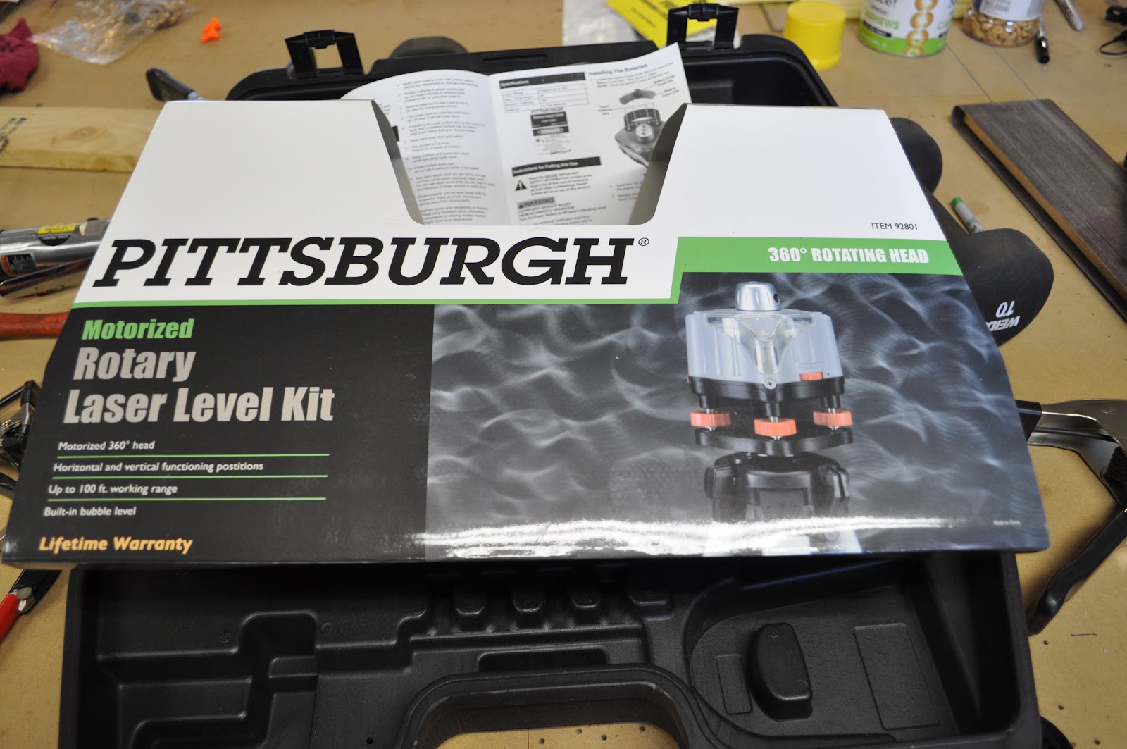
So, I bought a fairly cheap rotary laser from Harbor Freight. Out of the box, it comes with a tripod, rotating leveling laser head, and batteries.
The tripod is a little wobbly and needs to be adjusted carefully.
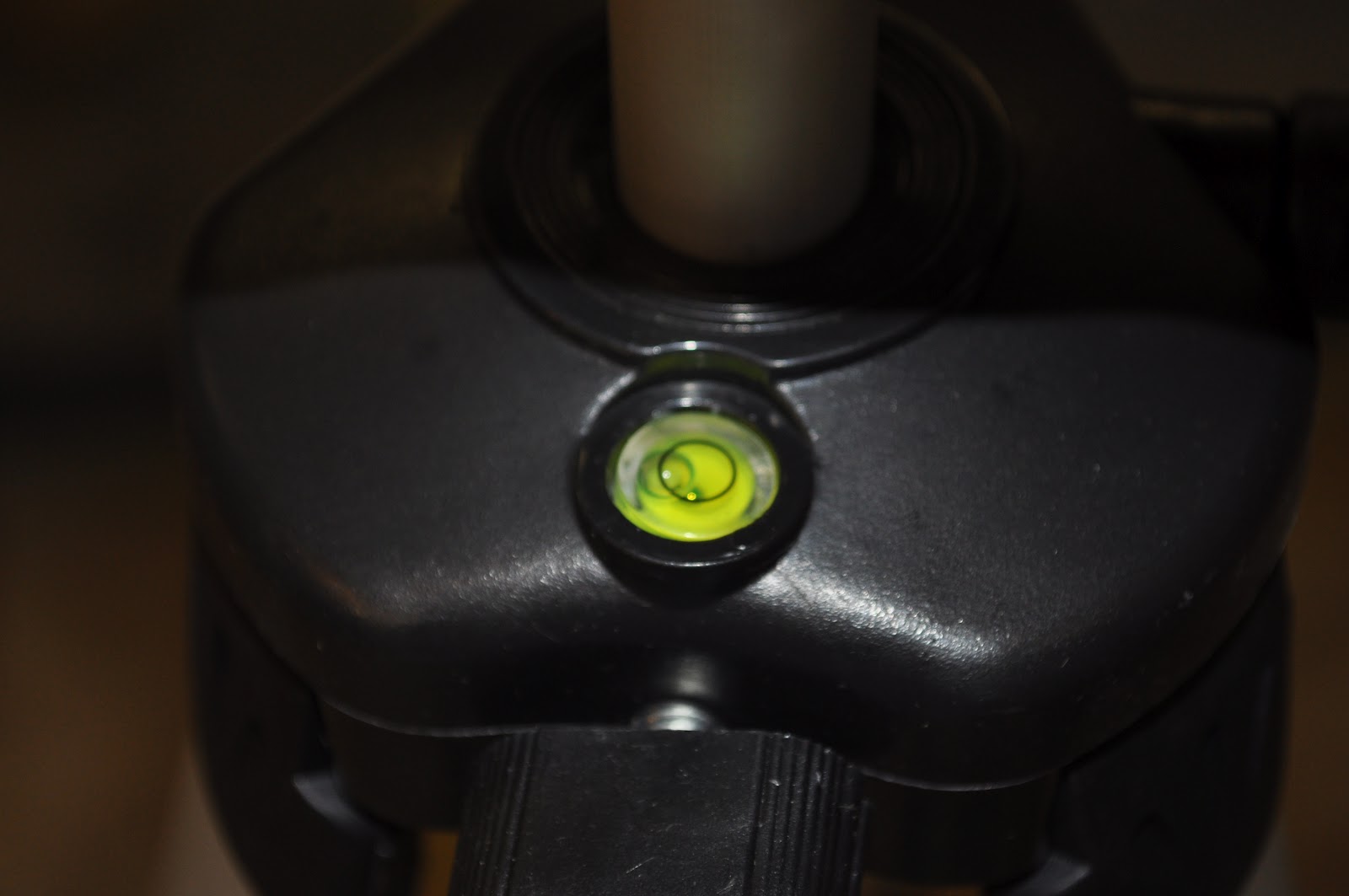
The laser is designed to mount to the tripod in either a vertical or horizontal direction. Here, I am adjusting the two bubbles for use in a horizontal direction.
The adjusting knobs allow for a fine adjustment. I was able to get the bubbles right where I wanted them.
There is a target type bubble on the tripod, but I found this one to be way, and I mean way out of adjustment. It was useless.
When ever using this system, I will have to be very careful. It is so wobbly. I may use some CA glue to "stiffen" it up.
Adjusting the horizontal bubbles.
Bubbles level and the laser is turned on.
I put on the red glasses that came with the laser so I can see the line.
BLARG!!! My worst fears have come true. The HRL is................
PERFECT!!!!
Right on the money. The laser showed up on my marked line all the way around the forward fuselage.
Although the tool is a little finicky, it will work great for the rest of the build. Now I can attack the tail cone and epinage.
One more tool coming from Harbor Freight this week. A pneumatic flanging press.
Later,
BWW
So, I bought a fairly cheap rotary laser from Harbor Freight. Out of the box, it comes with a tripod, rotating leveling laser head, and batteries.
The tripod is a little wobbly and needs to be adjusted carefully.
The laser is designed to mount to the tripod in either a vertical or horizontal direction. Here, I am adjusting the two bubbles for use in a horizontal direction.
The adjusting knobs allow for a fine adjustment. I was able to get the bubbles right where I wanted them.
There is a target type bubble on the tripod, but I found this one to be way, and I mean way out of adjustment. It was useless.
When ever using this system, I will have to be very careful. It is so wobbly. I may use some CA glue to "stiffen" it up.
Adjusting the horizontal bubbles.
Bubbles level and the laser is turned on.
I put on the red glasses that came with the laser so I can see the line.
BLARG!!! My worst fears have come true. The HRL is................
PERFECT!!!!
Right on the money. The laser showed up on my marked line all the way around the forward fuselage.
Although the tool is a little finicky, it will work great for the rest of the build. Now I can attack the tail cone and epinage.
One more tool coming from Harbor Freight this week. A pneumatic flanging press.
Later,
BWW
Monday, July 30, 2012
Oshkosh Week!
The week of Oshkosh has come and gone. Fairly fast as usual. I took the week off and did some building and I bought some more tools at Oshkosh.
Tonight I clamped bulkhead for station 114.75 in place. Once my 300 Clecos arrive, I will start assembling the tail cone and epinage. The bulkhead is on the center line and looking good.
I ordered a self leveling spinning laser level to check the horizontal reference line. (HRL) It should be delivered this week.
During the times I was not at Oshkosh, I made some headway on the forward fuselage. Made some final trim cuts on the side skins and the top skin.
Drilled #40 holes and Clecoed with the silver 3/32nd Clecos. When the 300 copper 1/8th Clecos arrive this week I will enlarge the holes.
Once enlarged & Clecoed, I will be able to work towards the tail!
I have also been playing around with the placement of the header tank. You can barely see the filler neck in this shot up against the upper skin.
Just about ready to drill a hole through the skin for the tank cap.
A new toy I picked up at Harbor Freight in Racine, Wi. A 30" sheet metal bender. It was pretty inexpensive and should come in handy for bending the tail doubler and other parts.
There was a pneumatic powered punch flange tool I am thinking of ordering.
Lots of fun, now it's back to work!
BWW
Tonight I clamped bulkhead for station 114.75 in place. Once my 300 Clecos arrive, I will start assembling the tail cone and epinage. The bulkhead is on the center line and looking good.
I ordered a self leveling spinning laser level to check the horizontal reference line. (HRL) It should be delivered this week.
During the times I was not at Oshkosh, I made some headway on the forward fuselage. Made some final trim cuts on the side skins and the top skin.
Drilled #40 holes and Clecoed with the silver 3/32nd Clecos. When the 300 copper 1/8th Clecos arrive this week I will enlarge the holes.
Once enlarged & Clecoed, I will be able to work towards the tail!
I have also been playing around with the placement of the header tank. You can barely see the filler neck in this shot up against the upper skin.
Just about ready to drill a hole through the skin for the tank cap.
A new toy I picked up at Harbor Freight in Racine, Wi. A 30" sheet metal bender. It was pretty inexpensive and should come in handy for bending the tail doubler and other parts.
There was a pneumatic powered punch flange tool I am thinking of ordering.
Lots of fun, now it's back to work!
BWW
Sunday, July 22, 2012
Progress so far...
So,here I am today. July 22, 2012. Still working on the forward fuselage. It is getting tighter to get into with each part I add to the plane.
I am placing and marking where some of the top skin braces go.
You can see the header tank brackets attached to the firewall.
The floor is held in place by 10/32 bolts into anchor nuts. The floor channels and tunnel are riveted together at this time. The side skins wrap around under and are Clecoed to the channels.

The forward fuselage with many Clecos holding it together. I have run out of the 1/8" copper colored Clecos again. When I am at Oshkosh this week I will try and get 300 more. (Probably 100 more of the 3/32" silvers.)
I have a few trim cuts on the side skins and top skin. Don't know if I should debur, dimple, & rivet, or start assembling the epinage. I will need to contact the builders group to see what others have done.
Shot of the progress so far. Lots to do!!!
I try and make a little progress each day. Sometimes it is very hard to do.
Slow and steady wins the race!
Later,
Brian
Can I fly yet?
I am placing and marking where some of the top skin braces go.
The floor is held in place by 10/32 bolts into anchor nuts. The floor channels and tunnel are riveted together at this time. The side skins wrap around under and are Clecoed to the channels.
The forward fuselage with many Clecos holding it together. I have run out of the 1/8" copper colored Clecos again. When I am at Oshkosh this week I will try and get 300 more. (Probably 100 more of the 3/32" silvers.)
I have a few trim cuts on the side skins and top skin. Don't know if I should debur, dimple, & rivet, or start assembling the epinage. I will need to contact the builders group to see what others have done.
Shot of the progress so far. Lots to do!!!
I try and make a little progress each day. Sometimes it is very hard to do.
Slow and steady wins the race!
Later,
Brian
Can I fly yet?
Saturday, July 14, 2012
July Up-date
Ok.It has been a while since I wrote anything in the blog. So, here is some of what I have been up to.
Lots of work in the forward fuselage. I took the lower channels off the plane and clamped them to the work bench.
I attached the bulkhead member between the lower channels and attached the rudder pedal support brackets to the forward fuselage tunnel.
Everything seems to fit OK. When I actually mount the rudder pedals in the plane I will need to make some minor adjustments to the assembly.
I placed a milk crate on the work bench and used it as a seat to check the feel of the rudder pedals.
I dis-assembled the pedals and placed them back in the box and up on the shelf.
After deburing I corrosion protected the the pieces and assembled them together while the paint was wet.
After riveting on the rudder pedal support brackets, I realized I may (and did) have a difficult time riveting the forward tunnel to the lower channels. I am still working this problem out.
Here is the assembly Clecoed to the firewall.
I riveted the tunnel between the firewall and the lower firewall angle while I had it clamped to the work bench.
I have found the more I can assemble on the bench the easier it is and the results are better.
The rivets for the engine mount bracket to the lower channels was the most difficult. I ended up making my own bucking bar in the mill to get around and under the channel.
You can see in this picture, the "wing" flap pieces of the firewall are bent at 90 degrees and slide between the lower channels and the engine brackets.
So far, this area of parts going together have been the most challenging to assemble.
I had the side skins off and drilled guide holes for drilling the assemblies rivet lines when I clamped it all together.
Here is a shot of the skin clamped in place.
This I was able to complete in February and March. I am further along then this.
I will be adding some more pictures and stuff in the near future to get caught up to where I am at.
Later,
Brian
Subscribe to:
Posts (Atom)